One of boating’s classic sayings is “the difference between an ordeal and an adventure, is attitude”. By and large, I agree.
Some months back, Yacht A Fun experienced an oil seal failure- right in the middle of day-sail charter season. Diann and I opted to have the situation inspected by mechanics to see if we could quickly replace the seal without significantly interrupting the revenue flow. For more details on the beginning of the “seal adventure” see previous blog post on that subject.
We have been living with the process since pulling the engine from its compartment.
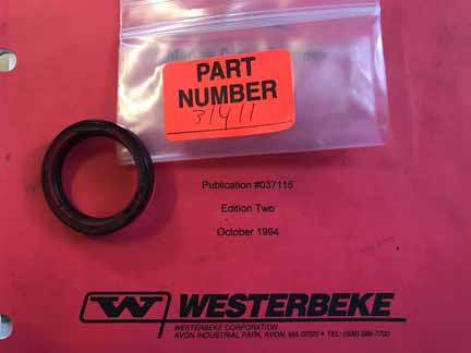
How could such a small part cost $55 plus freight?
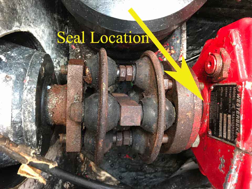
Why would the coupler manufacturer create a coupler that becomes integral to the engine and drive vs. removable from between the engine and drive?
( This blog will be more relevant to Gemini owners than other boat owners. But from the process we have developed, perhaps aspects of our procedures and obstacles will yield insight for your specific engine issues. )
Though he had assured us he could, our chosen mechanic was unable to remove the coupler to access the seal without moving the engine forward.
So, on the third visit day the engine was slid forward and the coupler was removed. However, it was determined that the transmission could not be removed without pulling the engine- as a number of the Allen head bolts were stripped due to lack of the ability to have perpendicular access to the bolt heads via the socket drive. Other aspects pointed to engine removal as well.

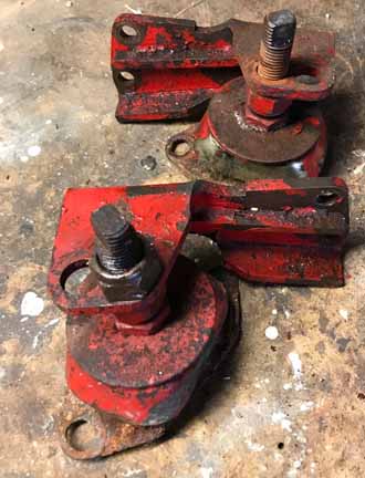
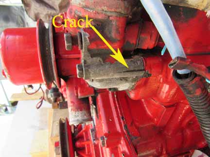
Diann and I were extremely frustrated with the situation. Yacht A Fun was inoperable for day sails. Initially we kicked ourselves for having not used “stop-leak” to slow the 4 ounces per engine hour of oil leakage. We could have gotten in a number of passenger trips during July, August, and September. However, after pulling the engine out, we discovered that the forward portside mounting foot had rust away to the point of being the culprit for the seal failure.
If we had used stop-leak to have kept running the transmission, we’d have probably ruined the transmission’s bearings in the process. The mechanic’s inability to execute seal replacement, without moving the engine, became a blessing for us in that the rusted engine mount was discovered as a result of that inability.

Engine to Outdrive alignment was gone when this mounting foot failed due to rust
Had we paid professionals to remove the engine for us we would have had a couple of choices:
#1- have the mechanic (and probably a helper at extra cost) bring a portable A frame rail rig from Beaufort to New Bern Grand Marina. Diann and I would have had to use our dingy to tow Yacht A Fun to the pump out dock for access to the A frame. Some wooden custom base would have had to be made to protect the boat’s decks. And after the engine would be hauled to Beaufort, the process would have to be done in reverse to get the engine back in its compartment on the boat.
Choice number 1 would have cost about $500 for each visit, plus all work would be done at their shop at their labor. Cleaning and repainting the engine would have not been affordable. Nor would replacing all water hoses.
Choice #2- was to tow Yacht A Fun about two miles to the Bridgeton Marina Boat Yard. There, the vessel could be pulled out via travel-lift and a separate crane used to pull the engine out where it could be placed into the mechanics van for transport back to the shop. Cost for travel lift, and crane, about $400 each way.
While Diann and I were on the trip mentioned in the first blog about the seal, I decided that pulling the engine myself would be the most beneficial solution. We’ll call it choice number 3.
Upon returning to New Bern after that trip, I visited the mechanics business location and spoke with the manager. He understood the initial miscue. If all goes to plan, I believe Diann and I will be happy with how the whole process will have unfolded. On that aspect— we’ll see. It’s still in process as you’ll read.
To design a Gantry Crane, I first sat in the cockpit, drank coffee, and pondered what steps would be needed to remove the engine.
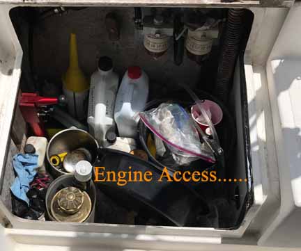
Given the tight opening, parts would have to be removed.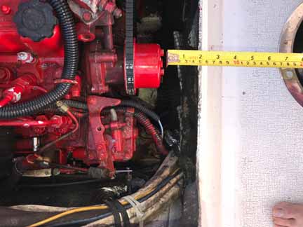
Before removing electrical connections for the alternator, and such, images would have to be taken so that “monkey see, monkey do” would be a reliable substitution for professionalism.

Choke, throttle, wiring, and coolant hose connections would have to be unfastened. Coolant water hoses to the hot water heater would have to be plugged.
The gantry beam for chain hoist support would have to be able to be rolled since the engine length exceeds the fore and aft opening of the compartment.
With those basics in mind, the area had to be measured horizontally and vertically in order to draft onto graph paper what the relationships would have to be. Pondering and first draft onto graph paper took up much of day one. Driving Cruise the Neuse for a river tour took up the other time.
About 4AM the next morning it occurred to me that I’d need access to the sides of the engine while lifting it. That meant the lids for the starboard and port lockers would have to be removed due to the width of the work table that would be integral to the gantry. ( Once the engine was removed and elevated, the 4’ by 3’ plywood would be supported and secured onto which the engine would rest during the needed repair and maintenance. )
The lockers would have to have a long term plastic sheet to shed rain.
Initially I conceived using a fore and aft 1” iron pipe with large pulley wheel as the support for the come along / winch. I bought multiple parts from multiple sources.
Thankfully, on another morning I had another 4AM wake up thought. So, I went to Ferguson Plumbing for verification of safety regarding iron pipe and relevant sizes. That counsel was valuable. The Ferguson manager suggested I consider using casters for rolling support. All the plumbing, and ancillary parts, were returned for refunds. Caster related parts were then purchased.

The design of the Gantry Crane was finalized. Captain Dave, of Cruise the Neuse, had scrap wood that could be incorporated. I bought 2×4 and 2×6 materials along with deck screws from Lowes hardware. The come along was about $25 from Walmart.
All together, I may have $200 in the Gantry Crane. And, the wood can be repurposed. The come along can go back to Hickory for storage.
The Gantry was completed, with allowance for work table components which would be attached after the engine was out and up.
The engine’s alternator was removed, and other components disconnected. Even the heat exchanger plates had to be taken off due to the width limitation.
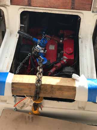
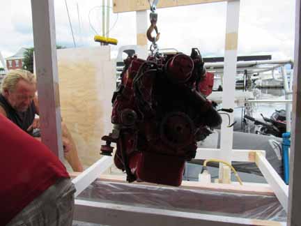
As Dave and I started the lifting, it became apparent that the front support arms would have to be removed to eliminate the feet from getting caught on wiring cables and compartment sides. It was at that point we confirmed just how bad the rusted foot flange was. But, with support arms and feet off, we wrestled the iron beast up. The rolling casters worked like a charm.
Once the table top was placed on two by four supports, and screwed down, the engine was rotated 90 degrees and placed on blocks to keep the oil pan from being crushed by the 350 pound engine weight.

It’s a BOY
Capt Dave helped

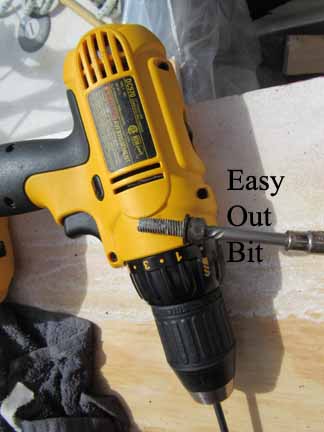
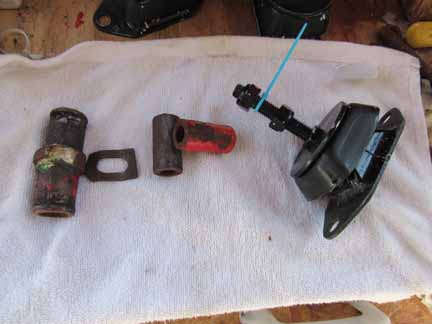
To begin getting access to the Allen bolt heads, the port side transmission cooling hose had to be disconnected from its two points of connection. The transmission connection was easy to free up. ( Using channel locks over the internal coupling, you can slowly rotate the hose to break it free. ) But, the hose end attached to the coupling simply would not come free. Using the channel lock approach only caused the steel bracket to bend ! So, I hack sawed the hose off so I could get on with using the Dremel and an Easy Out to extract the transmission’s troublesome bolts.

I spent three full hours working with the bolt, which had “smeared”. The mechanic had attempted to drill the heads off the offending bolts- while still down in the restricted space of the engine compartment. He drilled by feel since the heads were beyond view.
Finally, with a rubber mallet I was able to tap the transmission shell such that the gasket released and the transmission gave birth to itself. (LoL)
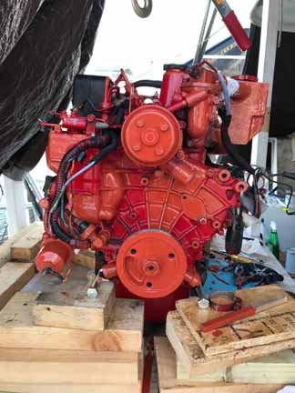
That afternoon, I headed to Beaufort with the transmission and seal. While the transmission was at the mechanic’s shop for the seal installation, I began a series of inspections and maintenance.
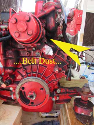
Using Simple Green, the engine was degreased and the black pulley belt dust was wiped off. Q-tips were used, as well as a tooth brush.
Hoses were labeled and removed.
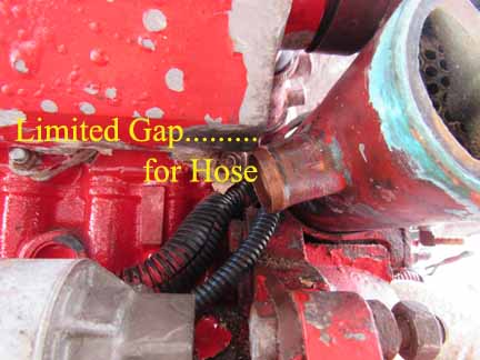
Note how tight the heat exchanger was to the coolant tank
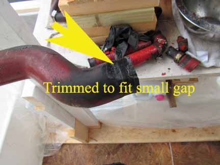
The previous installation tech had cut away hose to force the fit !
Amonia was used on uncooperative spots.
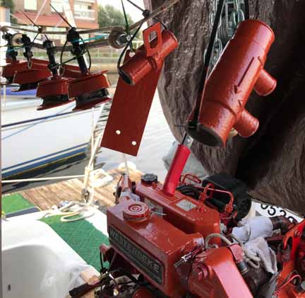
Coolant hose and engine mount parts were ordered from the Westerbeke supplier.
Westerbeke’s spray can of red paint is about $32. A quart of engine paint from POR-15 was $25 including freight. (ask for a coupon) Great humor on the POR-15 paint. The web site image indicated that Chrysler Hemi Orange was a version of red. HA HA HA
Chrysler Hemi Orange came to us the color of Texas Pete hot sauce. And that’s why we now call our engine “Pete the Beke”. One can readily tell the new paint from the original catsup red. The point of painting was to stop rust. Call it function over form.

A point to make about self etching primer. It is so thin that it will run between electrical connections on bolt posts. Though I had planned to proactively clean all the posts and terminals with 220 grit sandpaper and apply dielectric grease- that option became mandatory after using the primer on terminal posts.
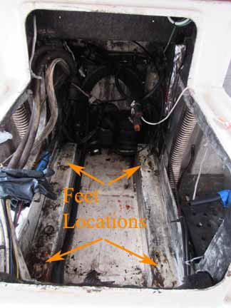
While waiting for painted parts to dry, I accessed the engine compartment and used the Simple Green and Amonia technique to clean it up as far as I could reach. White Rustoleum paint was applied so as to make the new engine feet easier to position over the bolt holes which seem black by contrast. BUT, when cleaning the support rails, dirt and oil fell into the little round openings such that grim was added to the rust of the treads. To clean the threads of the cast-in nuts, I’m having to use a die tool as if cutting new treads. Now who’d have budgeted that time into this project !
As seen before the cleaning
Other aspects have included:
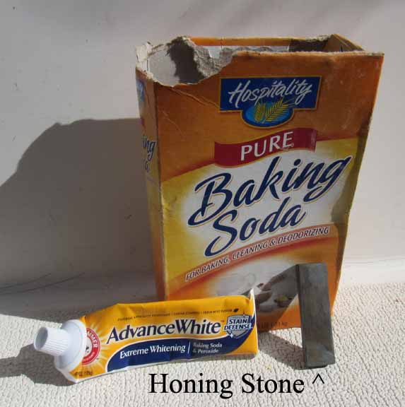
Used Honing Stone and tooth paste with baking soda to follow acetone cleaning of transmission sealant
On the engine mount
Cloth over gears during transmission sealant cleaning
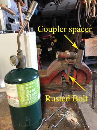
One of the bolts had seized to the spacer and so the spacer had to be heated to be able to use a hammer to drive out the bolt

Old feet were measured to set the new feet to same height. This should ease alignment.
But the new parts from Westerbeke don’t match the holes for the support arms…………. (2017 vs 1997)
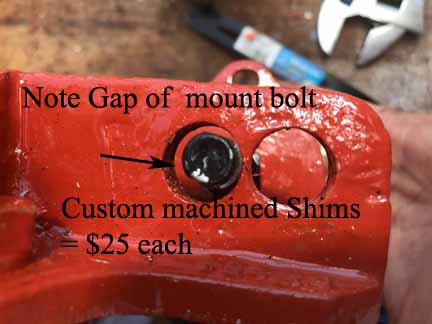
New bolts are smaller than original
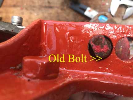
Note the flat part of the original bolt. It’s for placing an open face wrench.
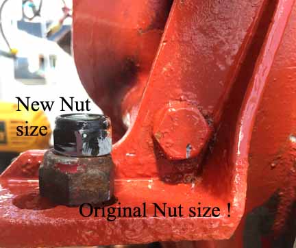
Washers will have to be used below and above the support arm to add bearing surface for support. The original nuts were large enough that washers were not needed.
Cleaning revealed potential future trouble items
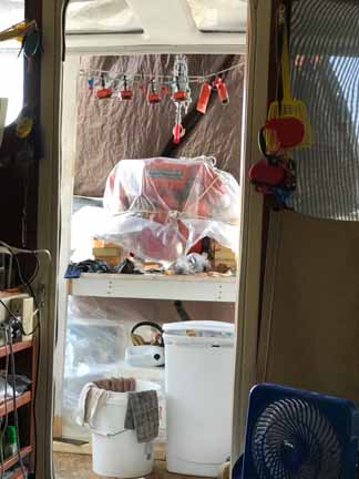
Yes, it still looks like this when we sit at our dining table!
The next phase begins with more cleaning of the transmission mating surfaces; installation of new hoses and clamps; and going to the Grill Man’s machine shop to pick up custom shims to make up for the Westerbeke motor mount feet bolts being smaller than the original parts. (Someone at westerbeke should have caught this glitch in parts. 5/8 bolt holes don’t mate properly with number 12 metric bolts.)
Three bolt images
Once the transmission mating surfaces are clean, it will be time for a dry fit. And the process will continue………………
The story / blog of Yacht A Fun, a Gemini catamaran sailboat, traveling the ICW and east coast with insights to the extended cruising life. Westerbeke Oil Seal for JS transmission